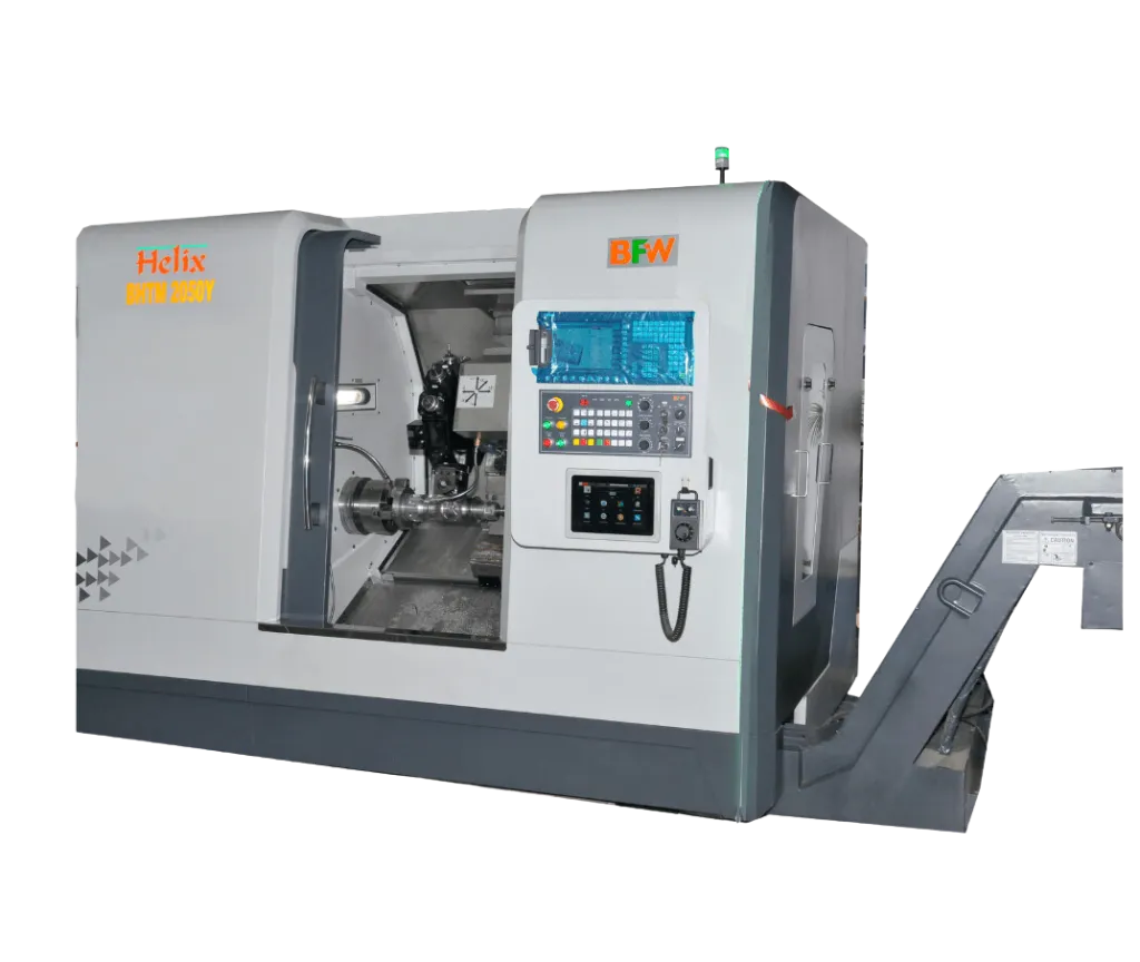
Helix Series machines are made with single-piece inclined bed cum saddle. They are built with heavy-duty LM guideways for rigidity and precise ball screws for higher accuracy.
The Servo turret of BMT 65 is provided as standard and it is the newest technology for turning mill center for more rigid solutions.
Spindle, turret, and tail stock axes are parallel to each other. It enables higher depth of cut.
Brand Story
Combining turning & milling technologies BFW developed a turn-mill version of the Helix series. Single setup, done-in-one to reduce lead time, achieves component accuracy & maximum efficiency. Ideally suited for a Wide array Of multi-process machining applications.
Helix Turn-mill, options to provide customer flexibility for fixture design to meet demands of cylindrical parts and simple interfacing that allows a wide range of machining applications. Best choice for completely processed prismatic work pieces.
Machines have been built with optimized structural rigidity and stiffness for ultimate performance and consistent results.
Adding Y axes with a Helix turn-mill for off-center operations like drilling, milling, tapping & eccentric boring, etc. Y moment is generated by interpolating to linear axes to increase the linear motion capability & achieve production advantage for your competitive manufacturing.
- Standard Features
- Unique Features
- Optional Features
- LM guide-ways for all axis – Class H
- High Precision ball screws- Class C3
- Belt-driven spindle
- AC servo drives for spindle & axis
- Linear & circular interpolation
- Laser calibration & Ball bar tested
- Rigid taping
- 12-station hydraulic turret
- Tool display
- Rigid tap retraction push button
- 3 jaw self-centering chuck
- Solid rotary cylinder
- Tail-stock with programable quill
- Coolant tank with chip tray
- Machine lamp
- Operations indication lamp-3 color
- AC unit for electrical cabinet
- Centralised lubrication system
- Maintenance tool kit
- Monoblock construction of bed cum saddle with an inclined angle of 45 deg for Helix and (30 + 45) deg for Helix with Y – axis
- Highest bar capacity 65 | 75 | 90
- BMT 65- Base mount type servo turret of 12 stations
- All 12 stations can be used for live tool applications
- Swivel operator panel for operator easiness
- Lesser loading height from the floor and lesser distance from the door for clamping heavy components
- Basic TPM features
- 2 & 4 jaw self-centering chuck
- Collet chuck
- Hollow cylinder
- Pneumatic operated Auto door
- Chip conveyor with chip bin
- Door safety limit switch
- Bar feeder
- Part catcher
- Steady rest
- Tool probe
- Work probe
- Automation solutions
- Tooled-up solutions
Specifications
| Specifications | Unit | HELIX 2050 Y | HELIX 2550 Y |
| Capacity: | |||
| Swing over bed | mm | 550 | 550 |
| Swing over carriage (Y at zero position) | mm | 280 | 280 |
| Admit between center distance | mm | 620 | 620 |
| Standard turning diameter (Y at zero position) | mm | 240 | 240 |
| Max component dia at Y+50 position | mm | 140 | 140 |
| Maximum turning Dia (Disc-80mm length) | 280 | 280 | |
| Interference-free turning dia(Tool collision dia with adjacent tool pocket) | mm | 224 | 224 |
| Max turning length between Tail-stock & Head-stock centre | mm | 500 | 485 |
| Max turning length from chuck hard jaw face to tallstock centre | mm | 410 | 395 |
| Work holding & tool holding: | |||
| Standard chuck size | mm | 250 | 250 |
| Bar capacity | mm | 65 | 74 |
| Turret indexing mechanism | type | Servo | Servo |
| Turret type | type | BMT 65 | BMT 65 |
| Turret center height | 100 | 100 | |
| Turning Tool Shank size (B x W) | mm | 25 * 25 | 25 * 25 |
| No of tools | No.s | 12 | 12 |
| Boring tool holder dia | mm | 40 | 40 |
| Spindle: | |||
| Spindle nose | type | A2-6 | A2-8 |
| Spindle bore | mm | 76 | 86 |
| Number of bearing front/ rear | No.s | 3/ 2 | 3/ 2 |
| Spindle bearing front/ rear | mm | 110/ 100 | 120/ 100 |
| Spindle speed | rpm | 3200 | 3000 |
| Live tool speed | rpm | 4000 | 4000 |
| No of live tool stations | No.s | 12 | 12 |
| Live tool spindle power | kW | 4.5 (Fanuc) | 5.6 (Siemens) | 4.5 (Fanuc) | 5.6 (Siemens) |
| Control system-Fanuc/ Siemens | |||
| Spindie motor power continues/ intermittent rating | kW | Fanuc - 11/ 15 | Siemens 11/ 16.5 | Fanuc - 11/ 15 | Siemens 11/ 16.5 |
| Full power range | rpm | Fanuc - 1000 - 1750 | Siemens 750 - 2400 | Fanuc - 1000 - 1750 | Siemens 750 - 2400 |
| Traverse | |||
| Cross slide movement (X axis) | mm | 200 (+140/ -60) | 200 (+140/ -60) |
| Longitudinal movement (Y axis) | mm | +/- 50 | +/- 50 |
| Longitudinal movement (Z axis) | mm | 525 | 525 |
| Rapid traverse (X axis) | m/min | 20 | 20 |
| Rapid traverse (Y axis) | m/min | 12 | 12 |
| Rapid traverse (Z axis) | m/min | 20 | 20 |
| Cutting feed rate | m/min | 0 - 10 | 0 - 10 |
| Tailstock | |||
| Quill diameter | mm | 80 | 80 |
| Quill traverse | mm | 100 | 100 |
| Base traverse | mm | 400 | 400 |
| Quill taper | type | MT - 4 | MT - 4 |
| Quill thrust force-Max at 15 bar | kgf | 300 | 300 |
| Fluid system | |||
| Coolant tank capacity | ltr | 160 | 160 |
| Coolant pump capacity | lpm | 200 | 200 |
| Lubrication tank capacity (servo 68) | ltr | 2.7 | 2.7 |
| Hydraulic tank capacity (Servo 68) | ltr | 40 | 40 |
| Hydraulic pump capacity | lmp | 20 | 20 |
| Hydraulic system pressure | bar | 35 | 35 |
| Accuracy as per ISO 230-2 | |||
| Positioning X/Z | mm | 0.01 | 0.01 |
| Positioning - C axis | arc sec | +/- 36 | +/- 36 |
| Repeatability - X/Z | mm | 0.007 | 0.007 |
| Machine installations: | |||
| Machine dimension W x D X H | mm | 3100 * 1850 * 2100 | 3100 * 1850 * 2100 |
| Total connected load | kVA | 35 | 35 |
| Machine Weight | kg | 4500 | 4600 |
Applications


Have Any Question?
Bharat Fritz Werner Ltd. (BFW) is a pioneering name in machine tools, manufacturing solutions, and technological innovation.
Follow us on
PRODUCTS


RESOURCES
BFW UPDATES
Subscribe to get notified about latest events, new products, industry insights and other updates from BFW, directly to your inbox.
Trusted Global Manufacturing Technology Partner
Copyright 2026 © BFW, Designed & Developed by Appac Mediatech Pvt Ltd
Get Quote
Are you looking for a product or service offer? Let us know your requirements and we will get back to you soon.
We will get back to you soon
Download the brochure
Download our comprehensive product brochure and learn how our products should support your needs.
